Thursday, March 31, 2011

Put your image in 3D space with a Position pass in Nuke, Relight an image with Nuke... and Maya

I’m going to explain two techniques that I didn’t invent or something, so no credit, but it did took me some time to figure out how it works. The reason why I’m doing two techniques at once is because it’s well in your advantage if you use them together. The placement of your image with a position pass has been used in the movie District 9 for I believe the placement of dust clouds and other things, and I’m using it actually for the same thing, positioning lights.


Sometimes you find yourself in need of some extra light on your image for some extra depth of detail, but going back to Maya can be a real pain in the ass. If you have a position pass and a normal pass of your render, it can really speed up your workflow.  I defiantly advise you to make these renders from the world coordinates and not from those of the camera. If your images are renderd with a local Normal pass and a local Position pass, the lights in Nuke’s 3D space won’t always match  because of the difference in coordinates. If you do everything in world space, they visually all add up.

- Download example files
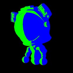
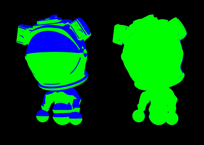

Normal

Creating a normal map in Maya is almost too easy. Render Settings -> Passes -> Create Render Passes -> Object Normal (World space) and hit Create and Close. Then approve the passes by selecting it and hitting the green button to put your new pass in the Associated Passes. 
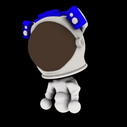
Position Pass

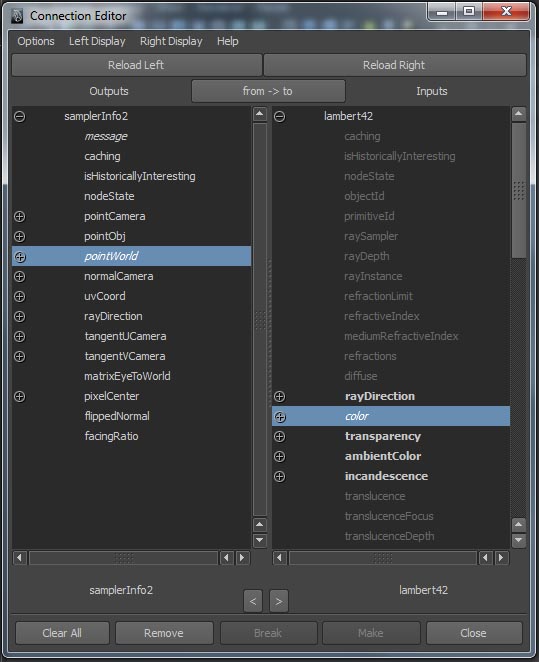
To make a Position Pass, you probably need a new render layer. I like to start with a new Lambert Material for this one and set the Ambient Color to full white, I know a Surface Shader can also be used, but I prefer the Lambert. Create a sampler Info Node and connect the Point World to the color of the Lambert, and that’s it. A position pass is an image that tells you where the points where in 3D space. It’s not exactly like this, but you can sort of see it as that the RGB value’s are the XYZ coordinates. Therefore, this image has to be a floating point image, like the 32 bit images. All done and hit render.


3D that image
You need to use a PositionToPoints node in Nuke for this. If I’m correct, the latest Nuke already has this plugin, so no need to download it. But how do you get this node? Two ways. Hit the X key and type “PositionToPoints” in the pop up and hit ok. Or…  go to Other and hit All plugins -> update. Then, go to Other again -> All plugins ->p -> PositionToPoints. Already got sweat on your forehead? Cause the hardest part is already over so relax. From the PositionToPoints node, connect the col to your Color image, and the xyz to your Position pass. Create a Light Node and a Scene Node end connect the scene node to the light, and connect the scene node to the PositionToPoint Node. Connect the viewer to this Scene Node or the PositionToPoints Node to see your image in 3D. Why you have the light? You’ll see.


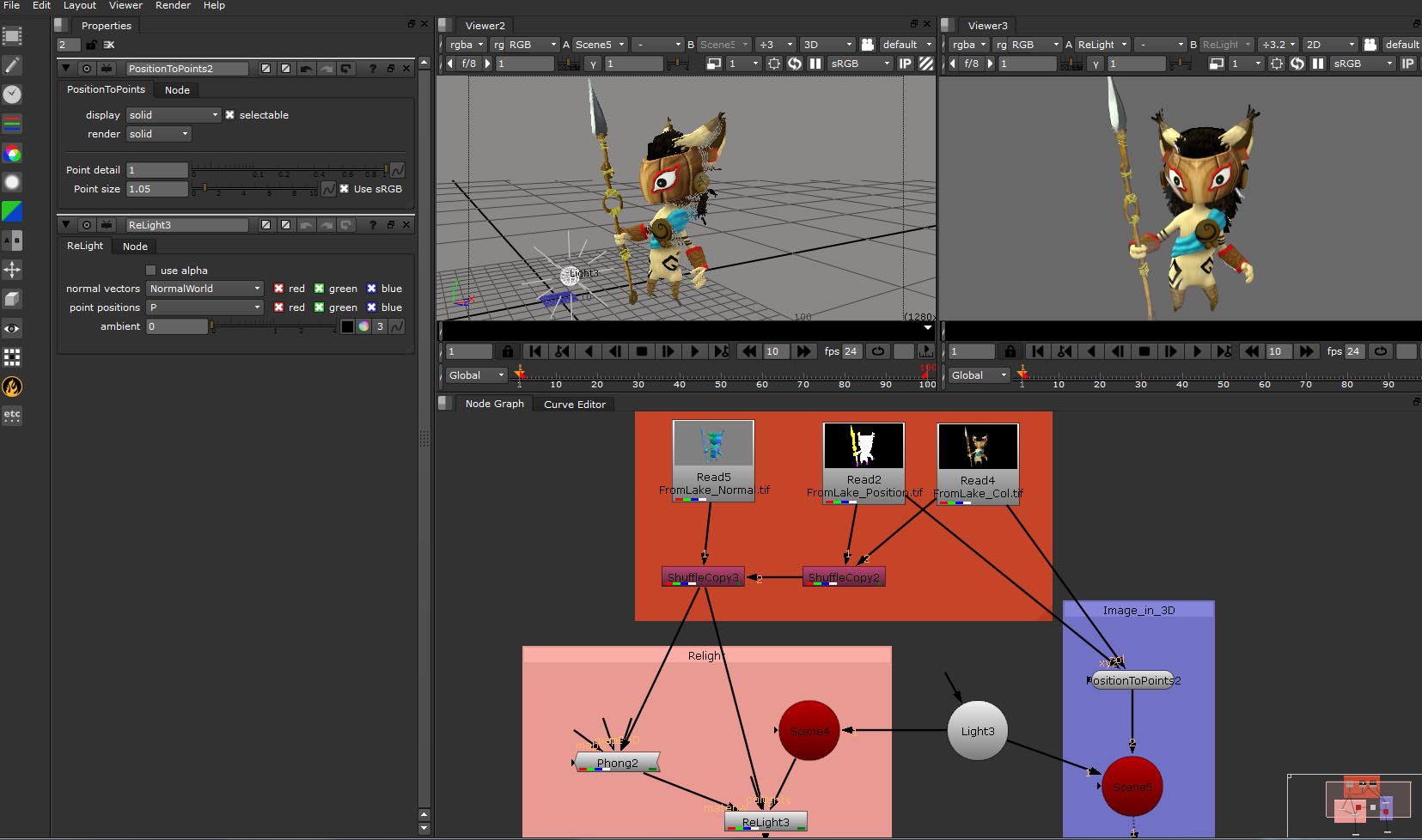
Relight with a Normal Pass
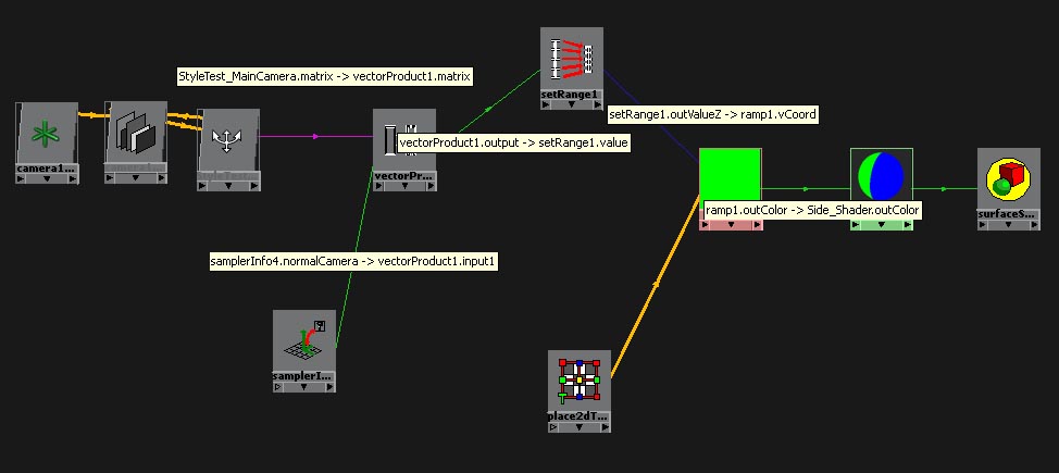
For this you’ll use the Relight Node, but for this little bugger to work you’ll need to put your color, Position and Normal Pass in one Node/Image/EXR with the help of the SuffleCopy nodes. If you don’t know how to do that, just check the file that you can download. To get the ReLight Node, update your plugins under the Other option just has before, if you haven’t done that already. I’m not saying the ReLight Node has bugs, but it’s not perfect either. Here it is. Connect the Color from your ReLight Node to the Node with all your image data and set the normal vectors to the Normal layer of your image, and the point position to your position pass. So far so good. Create another Scene Node and connect that scene to the already existing Light. Then connect the Lights from your ReLight Node to that Scene Node. For this thing to really work, you also need a material, like a Phong. So, create a Phong (just hit TAB and type Phong). But here to attach it??? Here comes the thing I was talking about. Connect the Phong to the ReLight Node, and you’ll see that the connection says, Camera. I don’t want a camera cause I want my image to be exact of how it was. What I like to do, CTRL click on the connection to create Dot. Break the connection between the Phong and the Dot, and connect the Phong again to your ReLight Node, now the connection says Material. You can delete the Dot if you like. If you want your phong to have the same colors as your image, connect the arrow with no description to your image, and you are set.

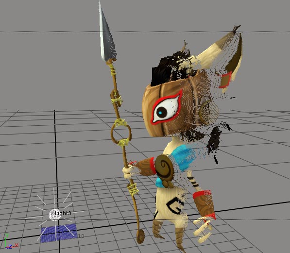
The reason for the PositionToPoints Node is that by having my image in 3D, I can visually set my light exactly as I want it in 3D space for my relighting. I can do this, because I connected the same light to both Nodes. And they are all true, because they are all in the same 3D space, world. 


Wednesday, March 30, 2011

A script to set my Maya scene

If I have to do the same thing over and over again in Maya, I’d like to make a script for it. Not only to prevent me from getting bored, but also to prevent mistakes that you will make when you are on automatic pilot. I’ve made a “simple” script that fits for my graduation movie, it stets my scene in Maya just the way I want it. Every time I create a new scene, I click on the button in my shelf with this new script, and it does the work for me, like resolution and the settings for file formats. By this, I know that the base of every scene in this project is the same. When I’m done with the scene and ready to render, I have another script for some other preferences that otherwise, I have to do over and over again for each scene before I can render. After those settings, I can make the adjustments or other settings specifically for that scene.

It’s not at all a high-end script, but it does make my life a whole lot easier.

Link:
- Start my Maya scene
- My basic rendersettings

How to bake an image sequence in Maya

I use an image sequence as a projection texture on several object in Maya 2011. Baking a texture, for instance the projection into the UV’s of the object, isn’t to difficult. But how do I bake an image sequence?

I found this script, km_bakeAnimatedTexture v1.0, by Kevin Mannens on www.highend3d.com. It was made in 2005 and it didn’t work anymore, atleast not in Maya 2011.
Because I was eager to make this script work, I looked at the script, I looked at all the fantastic scripts that my friend Roy Nieterau has made in our last project (CarKit Exodus) and I called back on my own Flash action script 2.0 knowledge from 5 years ago, and I fabricated this script.

Because the request on the internet for the solution of image sequence baking is pretty big, tadaah

Link:
- km_bakeAnimatedTexture_Maya2011-v1.1-

RB maps, side, front, top and diagonal

Front, side, top
I needed a RGB shader for a project with only two colors, for left and right, or top and down, front and back. The catch is, it had to be world orientated.  If my character was dancing, if my camera was hysterical and jumped from one place to another, the blue color for the right had to stay right of the world coordinates. See it as a light in my scene shining on my object, but without the light.


This shading worked perfect for the scene it was needed for. When you make it, you probably have switch the settings for the front a back shading with the left and right. Another thing is, the shading is very heavy in the viewport, but it renders extremely fast in your render. So a good tip is not to show shading and texturing in your viewport while working with this shading.

This is my model:


Create a Surface Shader and apply it to your model as a shader. Then create a Ramp and connect the Ramp’s outcolor to the outcolor of the Surface Shader. Set the settings of the Ramp to those as in the image below.


Create a setRange node, a VectorProduct Node, a SamplerInfo Node and get the node of your camera in the hypergraph as well (go to the cameras tab at the top and find that thing) Connect the Cameras Matrix to the Matrix of the VectorProduct. Connect the NormalCamera of the SamplerInfo Node to Input1 of the VectorProduct Node and set the drop down of the VectorProduct Node to Vector Matrix Product. Then connect the Output of the VectorProduct to the Value of the setRange. Set the Min in the setRange node to 0 for all three, the Max to 1, Old Min to -1 and Old Max tot 1.


And final, connect the OutValueZ from the setRange to the vCoord  of the Ramp.


If you want a shader for the back and front, top and under, just change the way you connect  the SetRange to the Ramp, for instance make it OutValueY instead of OutValueZ.


Diagonal
Lets make it difficult. Now I want this shading to be diagonal. Create an extra VectorProduct Node and place it between the other VectorProduct Node and the setRange Node. Set the new VectorProduct to Dot product and play with the numbers of the Input 2.


Result:


Anaglyph (stereoscopic 3D) colors

A small amount of time ago, far far away, I was all of the sudden very interested in stereoscopic 3D, maybe a good idea to use in my graduation movie. Because I don’t have the fancy equipment for Real 3D and others, or a 3D television, I returned to the good old and familiar anaglyph where you have glasses with a red colored glass, and a cyan colored glass. You probably know the deal with this, you have an image for your left eye that only contains the red channel, and an image for your right eye that contains the blue and green channel. So I did some tests with a normal photo camera to get me started. 


To see the real 3D effect, your eyes need the time to adjust for every image, just a couple of seconds before your really get into the dimensions of each photo. Very handy to know when you want to make your animation or something in 3D anaglyph.
But what you can already see in the first glance at these images, with your anaglyph glasses on, some colors are ghosting or dancing in the image. Terrible, that will give you some headaches. This happens because some colors can only be seen by the red glass, or the cyan glass of your anaglyph glasses. Earthly colors work best and the really bright saturated colors tent to screw up your image. That’s great information, but it doesn’t give me a great guideline to work with. So I made a graph who can tell me which colors are all right to work with, so I can prevent flickering and ghosting in my image. The graph became a movie because I needed three axes, X, Y and Z. X for the HUE (the color tint), Y is the Brightness and Z is the saturation that I placed in the timeline.


- which colors are all right to work with in a red and cyan anaglyph image - graph


This little movie is not bullet proof, it’s also not perfect, but it gives me a great guideline to start working with. If I pick any colors for my movies/animation that’s in the accepted are, not the striped area, it should all workout fine. If you look at the poster I made as a test (3 planes with normal maps and 3D text, no expensive modeling, and it already works great in stereo 3D from Maya).


Friday, March 25, 2011

32 bit linear workflow in Maya

Intro
What does 32 bit linear mean, what is it and how do I use it? 
When I searched for “32 bit linear workflow”, I had a hard time to find all the answers or to understand what several tutorials tried to explain. In the end I found most of my answers in the tutorials from Zeth willie and a Dutch book called “Basisboek, Digitale fotografie & beeldbewerking” (the basics, Digital photography & image manipulation) from Frans Barten. I will post a link to Zeth Willie blog below this text and I can definitely recommend for you to watch his tutorial about linear workflow as well! 32 bit linear workflow is not as much as a hard subject, but it is difficult to explain because you don’t know where to start. I‘ve run through this subject on a seminar that I did some time ago called “It all end with Nuke, linear workflow in Maya and compositing in Nuke” to second year students, and it went extremely well. So let’s start from the top.

8 bit images
Lets start with what you usually have. A jpeg file, a tiff file, a png file, ect. These are all 8 bit images. Now, what does that mean? Lets jump back a little bit more, to photography. Humans can only see about a couple of hundred
magnitudes of each color. That means, a few hundred magnitudes of red, a few hundred magnitudes of blue, and so on. The more colors/data a image has, the bigger its data size is.  One bit (a computers does everything in bits) has two options, on or off, an 8 bit image has 256 (2) options/colors for each channel. That’s perfect, because it’s just a little bit over of what we can see. So the normal 8 bit image you use, if probably a 3*8 bit image. 8 bits (256 colors) for the red channel, 8 bits for the green channel and 8 bits for the blue channel. RGB, Red, Green, Blue. Three channels, therefore the term, 3*8 bit image. When you also have an alpha channel in your image, you talk about a 4*8 bit image. So an 8 bit image is perfect for a final image, it has only the data that we can see as being a human, so the data size is pretty small. The values in a 8 bit image is between white, 0. and 255 (can also be displayed as 1), black.

32 bit images
What if we want to color grade an 8 bit image? If you change the exposure on your image, or the contrast, the brightness or whatever, you push and stretch the values of your colors. By example; place a line of marbles on your table (or on the floor, whatever works for you), and you can only see the marble that’s on every 2nd inch. If you bend and stretch the space between those marbles, you get big gaps between the marbles. If you now grab every marble that lies on every 2nd inch, you have a problem, because  there is not always a marble on the 2nd inch. Now you have a poor quality image. 32 bit images doesn’t have that fixed values between 0 and 255, but they are floating points, meaning that that they can have any value for each channel on each pixel, infinite. When you color grade a 32 bit image. You don’t change fixed levels like in a 8 bit a channel image, but you are changing infinite values. It is the best representation of the real world. Not all file formats can support 32 bit linear float. Files that do support can be uncompressed TIFF, EXR or HDRI.

RGB and sRGB
Monitors causes your image to be displayed much darker then they really are, this is called gamma. Monitors lower the gamma of your image by 0,455, this makes your images much darker. In Photoshop, you can play/find the gamma in the levels menu with the option in the middle of your histogram. The problem with this monitor thing is, we may see a mid-grey, color value of 127, but it’s not what it is. Photoshop deals with most of this gamma problem behind closed doors and by that you can’t get a really clear grip in this, “What I see is not what I have”. Later in this example I’ll use Nuke because of this. To contradict the effect of darkening the image, most images have a gamma of 2,2 to even it up and get a linear looking effect on your monitor, but it’s actually not. It’s a very lightened looking image displayed on a monitor who darkens it, and we meet in the middle. We get an image that looks true.


This effect of a gamma of 0.455 in your monitor is called sRGB, the gamma of 2.2 on a 8 bit image is pretty standard and can be found in images like Jpeg, Png, Tiff, ect. Usings a gamma of 1 (so you will see a darkened image on your monitor) is mostly used in 32bit linear float images like Uncompressed Tiff, EXR and HDRI images. It is also what we would like to have in compositing and color correction. We want this because color correction is nothing more than math with the values in your image. If we see a mid-grey of 127, it should calculate with the number 127 to get the math right, we don’t want the software to calculate with a completely different number then we see. These images, are linear, because the gamma on then image = 1.

This is what technicallyhappens;


Gamma of 1


Gamma of 0.455


Gamma of 2.2

32 bit linear workflow in Maya
Maya is a linear program, and that’s good. This prevents a lot of issues if we look at math again, but it also asks us to be aware of how we use the images that we throw in as textures, and that we render out.  The image that I render in Maya, like in this image below, is done in linear space and so this image is linear. But it is displayed on a monitor who uses a gamma of 0.455 to darken your image. Another thing to look out for, the textures that we use probably have a gamma of 2.2 and that’s why the images look correct in the render. We can deal with this in different ways and I shall explain of few of them.


Maya 2011 is blessed with a menu in the render view in which we can see, deal with this gamma problem of the monitor. Go to display -> Color Management, and switch the Image Color Profile to Linear. No you see a much render image like the second image up, in fact, now you see the image as it should be. We could also place a mia_exposure_simple (found in the Lenses section of the Mental ray nodes in your hypergraph) node to the Lens Shader input in the Mental Ray section of your camera from which you render. If you look at the Exposure Node, you’ll see a gamma input with a value of 2,2. (Don’t forget to turn the color management back to sRGB to see the correct result)


What about the texture? The texture has a gamma of 2.2. In order to fight against this, we can connect the image in a gamma Correct Node (you can find this node in the Utilities section of the Maya nodes in your hypergraph)  that we set to a value of 0.455 for all three inputs. The we connect the Correct Node to the input in the shader to which we want to connect the image to. With the Color Correct node, we de-gamma’d the image from a gamma 2.2 with 0.455, to get a linear image. No we have a linear image in linear space. You can see the result in the third image up. If you did it correct, your texture now, looks the same (apart from the lighting) as it did in the render before the gamma correction of the render.


Now, you could also use textures with a gamma of 1, like a uncompressed Tiff. I don’t like this method because it gives me another place on which to make errors. But, there is another way in Maya to deal with the gamma. That is called Frame Buffer, found under the Quality tab of you Render Settings. Set the gamma to 0.455, and Maya automatically renders your image with a gamma of 2.22 and resets your images with a gamma of 0.455 to create linear images. This actually creates a better looking image, that will probably be noticeable when you zoom into your image by 100 times. The bad thing about this technique is, that Maya will also gamma correct your bump maps, specular maps, normal maps, ect. And that’s not something that I always want. So I have to gamma correct those images in advance with, for instance, a Gamma Correct node that’s set to 2.2. Be aware, if you use a Physical sun and Sky, Maya automatically creates a exposure node to your camera. If you don’t want to gamma your image, of have this extra gamma on top of you frame buffer or color management, just set the gamma on this node to 1.

If we want to render out our images, we have to make a decision. Do we want to create linear images, of do we want to have sRGB images?

I want a 32 bit linear float image. To create a linear image, you need to set every gamma to 1, the frame buffer and/or your exposure nodes on your camera. To create a 32 bit image, we have to tell Maya to create a 32 bit image. Again, go to Framebuffer in the Quality tab of your Render Settings, and set the Data Type to RGBA (float) 4*32 bit. Go to the Common tab and select a Image format that supports 32 bit linear images, like TIFF uncompressed of EXR. Then render that shit out. (Batch Render that is, for 32 bit images, I would defiantly suggest to use the batch render)

I want a 8 bit image. Because it’s an 8 bit image, 256 color values, I want my image to have a gamma of 2.2 (also because people would expect this 8 bit image to be like this). go to Framebuffer in the Quality tab of your Render Settings, and set the gamma to 0.455. Or, if you use the exposure node on your camera, and set the gamma to 2.2. Set the Data Type in your frame buffer to RGBA (Byte) 4*8Bit and select an Image format, I like iff.

Nuke
Most of the time, I use Nuke for compositing. I think it’s an awesome program, but it also deals with the whole gamma story in a pretty good way. If you’re not familiar with Nuke, don’t be alarmed, I’ll guide you with the basic needs. Nuke uses a node based system and not a layer based system, so if you’re not familiar with this, brace yourself.
You can drag and drop your Gamma corrected image in the Node Graph, or you use the shortcut R (read) to create a Node to load your image. See the image below. To view the image, select and drag the arrow from the vieuwer1 node to your image. If you did it correct, the images should look pretty much the same in Nuke. That is because Nuke sets every image in to a linear space behind its c
urtains. This is again with the reason of right math. What we see, is what we have. To check this, hit you s key, and a properties window in being opened in the Properties Pane. Go to the LUT tab. Here you can see and change how Nuke will treat certain images in order to set them to a linear space. But wouldn’t the images be dark then? Yes they should, but we don’t want to color correct these images just yet, because we have to composite and color correct them. Just like the color Management in Maya, you can set the viewer to a sRGB space (which is default) by the dropdown menu at the top of the viewer.


Links:
- Zeth Willie, great tutorials and defiantly a blog to keep your eye on
- A fantastic tutorial on linear lighting and rendering for interiors